Loading
Technology
How PTDrone works
Two technologies make up PTDrone: the Autonomous Microfactory that builds the aircraft, and the single-engine VTOL turbojet UAV it builds.
Manufacturing platform
Autonomous Microfactory
The manufacturing platform, and the technologies that take an aircraft from a digital design to a tested, deployable UAV.
The process, in 6 steps
01 Microfactory Step 1 of 6
01.1 Digital Design
Digital Twin
A 3D model of the cell that simulates production runs and mirrors the process step by step.
PTDrone Control Center
One interface for production scheduling, part tracking and the state of every station.
01 Microfactory Step 2 of 6
01.2 Manufacturing
HP MJF Additive Manufacturing
HP Multi Jet Fusion fuses nylon powder layer by layer into detailed airframe parts, with many parts nested in a single build.
Powder Handling & Cooling
Builds cool in a controlled, enclosed unit, and unfused powder is recovered and blended back into the next build.
Automated Depowdering & Surface Finishing
Loose powder is removed in an enclosed cleaning station, then parts are finished to the surface the design calls for.
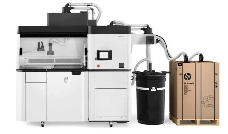
HP Jet Fusion 5200
MJF additive manufacturing
Image at risk Reseller photo, rights unconfirmed
01 Microfactory Step 3 of 6
01.3 Inspection
Machine Vision
Cameras locate parts for the robot and check each step as it completes.
3D Dimensional Inspection
A metrology-grade 3D scanner measures printed parts against the design model.
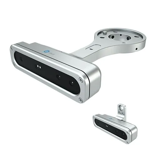
OnRobot Eyes
Machine vision
Image at risk Image-search copy, source unknown
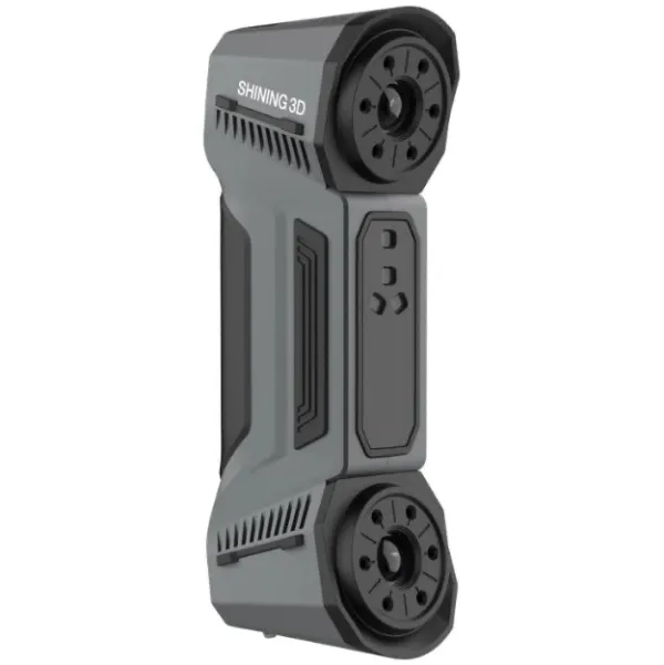
FreeScan Combo+
3D dimensional inspection
Image at risk Image-search copy, source unknown
01 Microfactory Step 4 of 6
01.4 Assembly
UR Robotic Material Handling
A Universal Robots collaborative arm moves builds and parts between stations.
UR Robotic UAV Assembly
The same arm picks parts, sets them in fixtures and joins them into the airframe.
Automatic Tool Changing
A quick changer lets the robot swap grippers, drivers and sensors mid-task, without an operator.
Automated Screwdriving
A robot-mounted driver sets fasteners to a controlled torque.
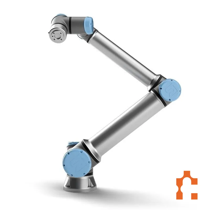
Universal Robots UR20
Material handling and UAV assembly
Image at risk Reseller watermark, rights unconfirmed
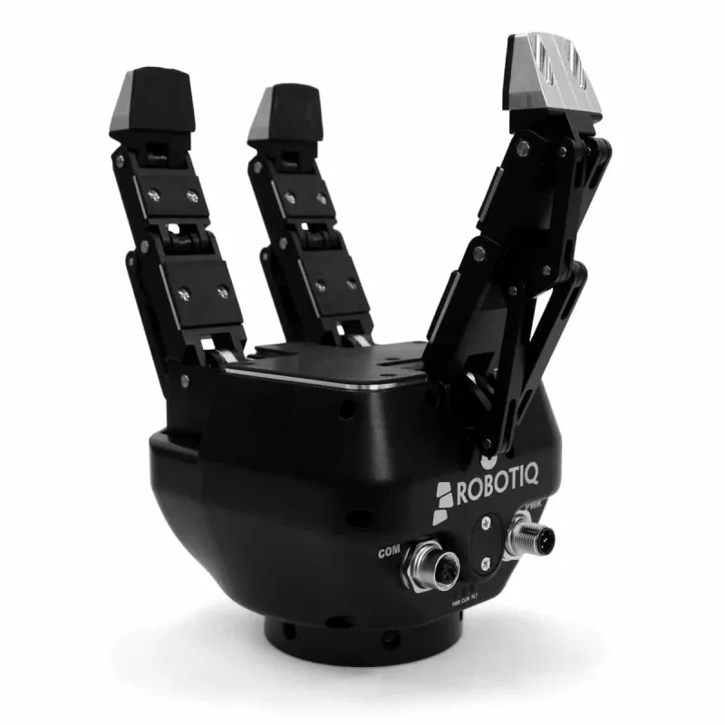
Robotiq 3-Finger Adaptive Gripper
Grasping parts of varied shape
Image at risk Reseller photo, rights unconfirmed
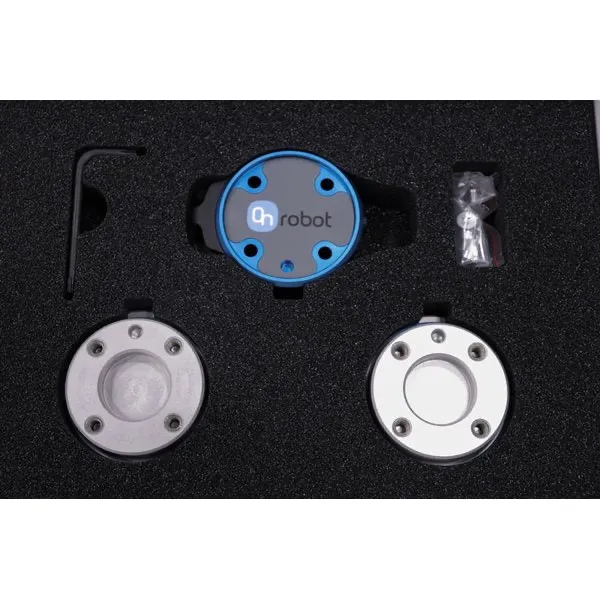
OnRobot Quick Changer
Automatic tool changing
Image at risk Reseller photo, rights unconfirmed
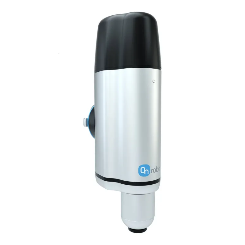
OnRobot Screwdriver
Automated screwdriving
Image at risk Reseller photo, rights unconfirmed
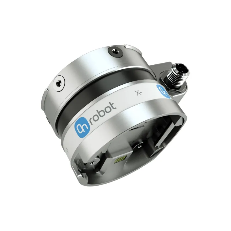
OnRobot HEX-H QC
Force and torque sensing for assembly
Image at risk Reseller photo, rights unconfirmed
01 Microfactory Step 5 of 6
01.5 Testing
Electronics & Flight Control Testing
Wiring, avionics and the flight controller are checked before an aircraft leaves the cell.
01 Microfactory Step 6 of 6
01.6 Deployment
GCS Integration
The ground control station and the factory share one record of each aircraft, from build order to mission.
Digital Production Record
Every aircraft carries a record of how it was printed, finished, assembled, inspected and tested.
Aircraft platform
Single-Engine VTOL Turbojet Fixed-Wing UAV
The aircraft platform itself.
Core concept
VTOL flexibilityFixed-wing efficiencyTurbojet high-speed capability
02 VTOL Turbojet UAV
Main components and technologies
Single-Engine Turbojet Propulsion
One turbojet provides the thrust for high-speed forward flight.
VTOL Takeoff & Landing System
Takes off and lands vertically, so it does not need a runway or a launcher.
Fixed-Wing High-Speed Flight Configuration
Once airborne, the wing carries the aircraft for efficient, high-speed cruise.
Modular Airframe Architecture
Sections swap out, so one airframe can be repaired or reconfigured for a different mission.
Lightweight Structural Design
Material is placed where the loads are, keeping the structure light.
Additively Manufactured Components
Airframe parts are printed in the Microfactory, where and when they are needed.
Integrated Flight Control System
One flight control system manages vertical flight, transition and wing-borne cruise.
Autonomous Navigation
Flies planned routes on its own, with the operator supervising.
Mission Payload Integration
Mounts and interfaces for cameras, sensors and other mission payloads.
PX4-Based Avionics
Built on PX4, the open-source autopilot, communicating with ground software over MAVLink.
Ground Control System Integration
Missions are planned, monitored and logged through the PTDrone ground control station.
Digital Twin / Vehicle Simulation
The aircraft is simulated to try configurations and missions before it flies.
02 VTOL Turbojet UAV Propulsion subsection
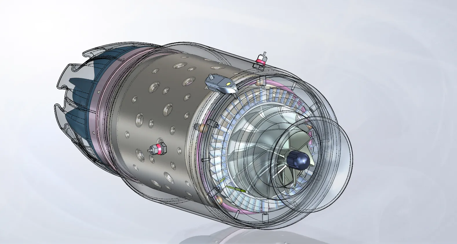
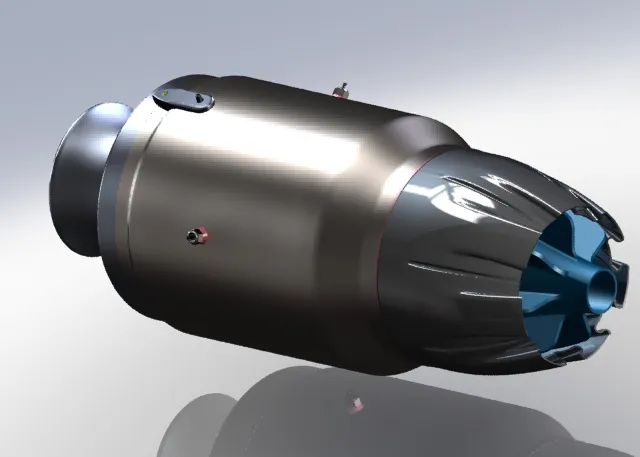
02.1 Metal Additive Manufactured Turbojet Engine
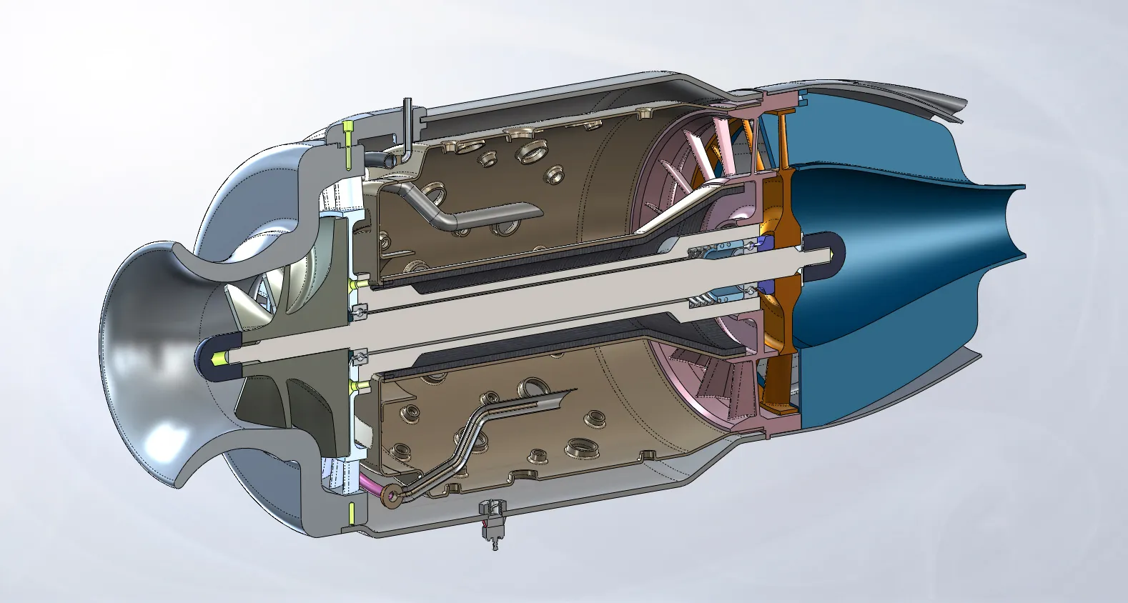
Metal Additive Manufacturing
Engine parts are printed in metal, layer by layer, directly from the design model.
Complex Internal Geometry
Internal passages and forms that cannot be machined or cast can be printed.
Integrated Cooling Channels
Cooling passages are built into the part walls rather than added afterwards.
Lightweight Engine Components
Material only where each part needs it.
Reduced Part Count
Assemblies of several machined pieces become single printed parts, with fewer joints.
High-Temperature Materials
Hot-section parts use alloys that keep their strength at combustion temperatures.
Combustion Chamber Manufacturing
The combustion chamber and its fuel and air paths are produced by metal printing.
Turbine / Nozzle Components
Turbine and nozzle parts are made by the same process.
Rapid Design Iteration
A design change goes straight to the printer, not to new tooling, shortening each revision.
Design for Additive Manufacturing (DfAM)
Parts are designed for printing from the start, not adapted from designs meant for machining.
Engine Performance Testing
Thrust, temperatures and fuel flow are measured on a test stand.
Thermal and Structural Validation
Parts are validated against the heat and loads they will see in operation.